
Tuesday
Jan102012
Process Flow or CAD View
When you create a simulation model, there are two fundamental world-views to consider; you can view your model from a process flow standpoint or you can view it from a physical layout standpoint. Sometimes the two views are similar, but more often they are quite different. This is a fundamental design decision that should be addressed at the beginning of the project. It will dictate how your simulation is configured, how data is fed into it, and how results are collected and interpreted. It may even change the way you think about the system.
To give you a concrete example, consider a situation that comes up often in our healthcare modeling work - examination rooms. In the physical layout world-view, the examination room might be treated as a single simulation object (it could be modeled as either a storage bin or a work center, but that's a whole post on its own). This approach makes sense graphically as you can place the exam room on a CAD layout and easily animate the patient as she enters and leaves the room. In most examination rooms, however, mulitple tasks take place, each with its own resource needs and timing. At a minimum, there is usually a nurse interview followed by a physician exam. With a little finesse, these multiple process steps can be managed in the single-object exam room (or physical layout) approach, but it is much simpler for novice simulationists to use a process flow approach instead, using separate objects for each process step. In this case, you'll still need to represent the physical constraint of the single exam room (using a group, for example; but this too is a subject for another post).
We find that when most people begin thinking of a simulation model, they often tend to view everything in terms of a physical layout (CAD). We suspect that it is because humans are naturally ‘spatial thinkers’. A recent client insisted that we develop their simulation according to the process flow methodology which led to a renewed level of respect for this approach.
On another recent project, the client only supplied us with physical layout diagrams. At first we were thrilled that we had such good information on the physical capacity; however, the physical layout doesn't necessarily tell us much about how more than 40 different products flow through several hundred work centers. In order to build an accurate model, we had to gather product flow information as well and incorporate it into specific station routing and process time logic.
Here, we'll tell you a bit more about each approach and outline the pros and cons of each to assist you in determining which methodology best matches your project.
Process Flow
The process flow view looks at the system from the perspective of the work items that move through it. Each type of work (Part A, B, and C) will have its own process flow with each operation explicitly defined. In the flow chart below it is easy to follow the steps that are required to assemble Part ABC which is composed of an AB part and a C part. AB parts are assembled from Part A and Part B.
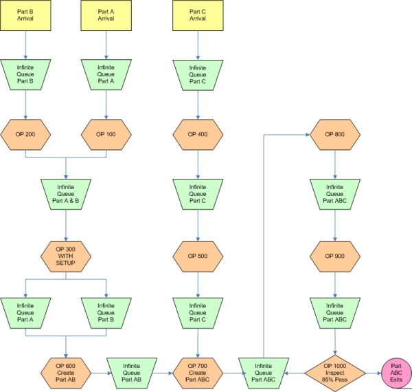
In a process flow approach, we would use SIMUL8’s work centers to represent each of the steps in the process (operations). In this example, it would be OP 100, OP 200, …, OP 1000. The work centers are not necessarily physical locations. In order to capture the constraint that the physical locations have on the system, we would include SIMUL8’s resource object as a requirement of the work centers.
Physical Layout (CAD) View
The CAD view, on the other hand, represents a physical layout methodology for building a simulation. Instead of using a flow chart as our point of reference, we would use a layout drawing of the facility. Let's revisit the example above, this time from a physical layout perspective. Our physical locations include assembly benches, testing, a curing oven, and an inspection station.
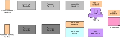
SIMUL8’s work centers would be used to represent these 8 physical locations. The challenge then becomes how do we route work items from one work center to another (or back to itself if sequential operations actually occur at the same location)? A second challenge would be the fact that the process time at a work center is dynamic, meaning it changes based on which work item is being processed, and which step in the process is being executed.
|
Operation |
Part |
Physical Location |
|
OP 100 |
A |
Assembly Bench 1 or 2 |
|
OP 200 |
B |
Assembly Bench 1 |
|
OP 300 |
A or B |
Assembly Bench 2 |
|
OP 400 |
C |
Assembly Bench 1 |
|
OP 500 |
C |
Bench 1 |
|
OP 600 |
Create AB |
Bench 1 |
|
OP 700 |
Create ABC |
Bench 2 |
|
OP 800 |
ABC |
Test Bench |
|
OP 900 |
ABC |
500F Oven |
|
OP 1000 |
ABC |
Inspection |
Clearly, the same underlying process can lead to two very differently structured simulation models. The following table highlights some differences of the two approaches:
|
Concept |
Process Flow Model |
Physical Layout Model |
|
Operations |
Unique work center for each operation. |
Dynamic adjustment to a work center’s resource requirements, process time, and routing based on the next/current item to be processed. |
|
Queues |
Single queue for each operation. |
Single queue for each bench. |
|
Bench |
Constrained using a resource. |
Unique work center for each bench. |
|
Routing |
Simple serial routing. |
Dynamic routing based on the part and step. |
|
Process Time |
Simple process time unique to each work center. |
Dynamic process time based on the part and step. |
|
Labor |
Static resource assignment for each work center. |
Dynamic resource requirement based on the next item to be processed (part / step). |
|
Results Collection |
Results must be accurately combined to match to real world or custom results must be collected.
|
Queuing results can be easily translated to the real world as the queues match physical locations. Work center utilization is clean and matches real world.
|
|
Graphical Presentation |
Simulation model will be abstract but may acutely reflect existing and familiar flow charts. |
Simulation will match physical layout including existing CAD drawings. |
|
Flow chart Import |
Possible to achieve substantial time savings as automatic importing may capture significant sections of your simulation. |
Not practical as the flow charts and the physical layout may have no resemblance. |
Conclusion
There are certainly pros and cons to both approaches. The process flow methodology is generally much easier to implement. The downside is that it may not give you the best, most useful, and most flexible simulation model possible. You may very well choose the process flow methodology for some simulations, while the CAD or physical layout methodology may suit other projects better. What is certain is the fact that you need both process flow diagrams as well as physical layout documents in order to accurately develop any simulation model.
Acknowlegement
Thanks to Raytheon Company for their contribution.
tagged  CAD, Process Flow, Work Flow in Development
Development