
Wednesday
Jun292011
Critical Path Analysis
Problem
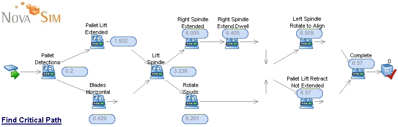
A potential client came to us in their search for simulation software. They wanted to understand how SIMUL8 could be applied to critical path analysis within a production machine that had many complex parallel steps. If they could easily understand the critical path elements, they could focus their attention on the best process steps for overall cycle time reduction. In this example, all process times are deterministic (fixed distributions with no variation).
Below is a simple example of a series of parallel processes. The values displayed (using SIMUL8's data graphics feature) contains the amount of time for an individual work item to complete the associated step and are included for information only.
Solution
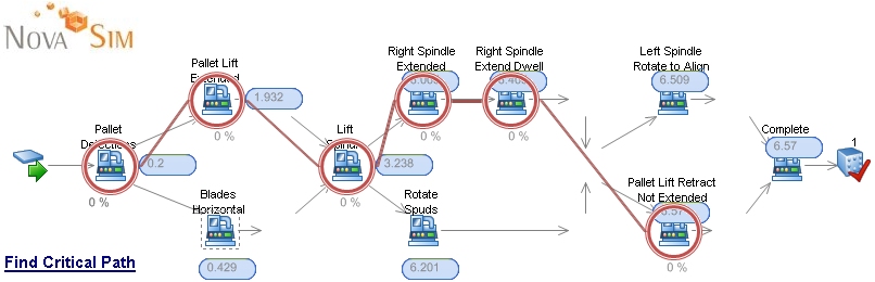
To identify the work centers which are on the critical path, let's first refer back to the definition of a critical path. If the change in process time of a work center results in a change in total cycle time (time in system), then the work center is indeed on the critical path. To demonstrate this, we added some control visual logic code to automatically run a series of scenarios, decreasing the operation time of each work center by a very small amount of time. We then compared the resulting cycle time to that of the bench mark. If the new cycle time was less than the bench mark, then that work center was indeed on the critical path. The simulation automatically repeated the experiment for each work center one at a time, recoding, in an information store spreadsheet, the result (1: on the critical path, or 0: off).
At the conclusion of all of the scenario runs, the simulation (using viusal logic Display+ commands) diplays red circle images overtop the workcenters, which are indeed on the critical path, and draws an arrow from one critical path work center to the next. Below is an image of the resulting critical path analysis.
Summary
1. Run a base line simulation to establish the standard cycle time per the inputs.
2. Run a different simulation for each work center in the model whereby the process time for each workcenter is decreased by (0.01) time units. If the total cycle time decreases when compared to the standard, mark the work center as a critical path element.
3. Add graphical indications to the simulation identifying the critical path work centers.
Application
Critical path analysis has traditionally been associated with project management efforts. In this case, it is applied to process steps within a machine cycle. The potential client who requested this had been frustrated with simulation software in which a cirtical path solution had not been available. Although this example is very trivial, the same approach can be applied to machine cycles which have many serial and parallell, interacting process steps.
References (255)
References allow you to track sources for this article, as well as articles that were written in response to this article.
-
 Response: backlink indexing serviceSuperb Web-site, Continue the excellent job. Appreciate it!
 -
Response: pokerinfinity blog writing serviceSimulation-based solutions from Novasim - SIMUL8 Experts - Learning SIMUL8: The Complete Guide to Simulation - Critical Path Analysis
-
Response: visit the next internet siteSimulation-based solutions from Novasim - SIMUL8 Experts - Learning SIMUL8: The Complete Guide to Simulation - Critical Path Analysis
-
Response: http://xovilichter.eu.comSimulation-based solutions from Novasim - SIMUL8 Experts - Learning SIMUL8: The Complete Guide to Simulation - Critical Path Analysis
-
Response: http://xovilichter.eu.comSimulation-based solutions from Novasim - SIMUL8 Experts - Learning SIMUL8: The Complete Guide to Simulation - Critical Path Analysis
-
Response: relatedSimulation-based solutions from Novasim - SIMUL8 Experts - Learning SIMUL8: The Complete Guide to Simulation - Critical Path Analysis
-
Response: Read the Full ReportSimulation-based solutions from Novasim - SIMUL8 Experts - Learning SIMUL8: The Complete Guide to Simulation - Critical Path Analysis
-
Response: establishing muscleSimulation-based solutions from Novasim - SIMUL8 Experts - Learning SIMUL8: The Complete Guide to Simulation - Critical Path Analysis
-
Response: Dexter YagerSimulation-based solutions from Novasim - SIMUL8 Experts - Learning SIMUL8: The Complete Guide to Simulation - Critical Path Analysis
-
Response: yelp.comChemists can use isotope analysis to assist analysts with issues in anthropology, archeology, food chemistry, forensics, geology, and a host of other questions of physical science. Analysts can discern the origins of natural and man-made isotopes in the study of environmental radioactivity.
-
Response: Bench Craft CompanySimulation-based solutions from Novasim - SIMUL8 Experts - Learning SIMUL8: The Complete Guide to Simulation - Critical Path Analysis
-
Response: bench craft company linkedin pagesSimulation-based solutions from Novasim - SIMUL8 Experts - Learning SIMUL8: The Complete Guide to Simulation - Critical Path Analysis
-
Response: My SourceSimulation-based solutions from Novasim - SIMUL8 Experts - Learning SIMUL8: The Complete Guide to Simulation - Critical Path Analysis
-
Response: Bench Craft CompanySimulation-based solutions from Novasim - SIMUL8 Experts - Learning SIMUL8: The Complete Guide to Simulation - Critical Path Analysis
-
Response: please click the next webpageSimulation-based solutions from Novasim - SIMUL8 Experts - Learning SIMUL8: The Complete Guide to Simulation - Critical Path Analysis
-
Response: Recommended Looking atSimulation-based solutions from Novasim - SIMUL8 Experts - Learning SIMUL8: The Complete Guide to Simulation - Critical Path Analysis
-
Response: bench craft companySimulation-based solutions from Novasim - SIMUL8 Experts - Learning SIMUL8: The Complete Guide to Simulation - Critical Path Analysis
-
Response: job description business analystSimulation-based solutions from Novasim - SIMUL8 Experts - Learning SIMUL8: The Complete Guide to Simulation - Critical Path Analysis
-
Response: new shoes on the feet
-
Response: software on Filehippo
-
Response: Portable apps com
-
Response: education appneet exam,biology for neet, neet biology, medical exam preparation, learning app for neet, neet learning app, selfstudy app for neet, study app for neet, best leaning app for neet, neet exam app, engineering entrace exam, chemistry for Class 11, chemistry for Class 12, chemistry for IIT JEE, chemistry for NEET, chemistry ...
-
Response: iit jee chemistry“NEET, IIT JEE Preparation app” Selfstudy app is the best study app for IIT JEE mains & Advanced|NEET and other Engineering, Medical, Foundation Entrance Exams BITSAT|CET|AIIMS|AIPMT etc. and also best learning app for Class 8, 9, 10, 11, 12th board exams CBSE|NCERT. NEET|JEE mains mock test, NEET|JEE mains test series, NEET|IIT ...
-
Response: chemistry for iit jee“NEET, IIT JEE Preparation app” Selfstudy app is the best study app for IIT JEE mains & Advanced|NEET and other Engineering, Medical, Foundation Entrance Exams BITSAT|CET|AIIMS|AIPMT etc. and also best learning app for Class 8, 9, 10, 11, 12th board exams CBSE|NCERT. NEET|JEE mains mock test, NEET|JEE mains test series, NEET|IIT ...
-
Response: iit jee app“NEET, IIT JEE Preparation app” Selfstudy app is the best study app for IIT JEE mains & Advanced|NEET and other Engineering, Medical, Foundation Entrance Exams BITSAT|CET|AIIMS|AIPMT etc. and also best learning app for Class 8, 9, 10, 11, 12th board exams CBSE|NCERT. NEET|JEE mains mock test, NEET|JEE mains test series, NEET|IIT ...
-
Response: byjus applearning app, study apps, selfstudy app, self study app, educational app, education app, byjus app, byjus, toppr app, extramarks, gradeup, gradeup app, allen, gradeup test series, jee main test, jee test, jee test series, jee main mock test, ncert, ncert solutions, jee advanced
-
Response: toppr applearning app, study apps, selfstudy app, self study app, educational app, education app, byjus app, byjus, toppr app, extramarks, gradeup, gradeup app, allen, gradeup test series, jee main test, jee test, jee test series, jee main mock test, ncert, ncert solutions, jee advanced
-
Response: Home Remedies of Allergy
-
Response: iit jee learning app“NEET, IIT JEE Preparation app” Selfstudy app is the best study app for IIT JEE mains & Advanced|NEET and other Engineering, Medical, Foundation Entrance Exams BITSAT|CET|AIIMS|AIPMT etc. and also best learning app for Class 8, 9, 10, 11, 12th board exams CBSE|NCERT. NEET|JEE mains mock test, NEET|JEE mains test series, NEET|IIT ...
-
Response: learning app for neetneet exam,biology for neet, neet biology, medical exam preparation, learning app for neet, neet learning app, selfstudy app for neet, study app for neet, best leaning app for neet, neet exam app, engineering entrace exam, chemistry for Class 11, chemistry for Class 12, chemistry for IIT JEE, chemistry for NEET, chemistry ...
-
Response: iit jee study appiit jee advanced, iit study app, neet preparation app, jee preparation, iit jee chemistry, iit jee preparation app, toppr, iit jee question bank, neet doubts, iit jee physics, iit jee maths, aiims entrance, jee doubt, iit jee, neet physics, neet app, jee mains, iit jee question paper, medical entrance exam, byjus, ...
-
Response: iit jee learning app“NEET, IIT JEE Preparation app” Selfstudy app is the best study app for IIT JEE mains & Advanced|NEET and other Engineering, Medical, Foundation Entrance Exams BITSAT|CET|AIIMS|AIPMT etc. and also best learning app for Class 8, 9, 10, 11, 12th board exams CBSE|NCERT. NEET|JEE mains mock test, NEET|JEE mains test series, NEET|IIT ...
-
Response: iit jee maths“NEET, IIT JEE Preparation app” Selfstudy app is the best study app for IIT JEE mains & Advanced|NEET and other Engineering, Medical, Foundation Entrance Exams BITSAT|CET|AIIMS|AIPMT etc. and also best learning app for Class 8, 9, 10, 11, 12th board exams CBSE|NCERT. NEET|JEE mains mock test, NEET|JEE mains test series, NEET|IIT ...
-
Response: chemistry for AIIMSneet exam,biology for neet, neet biology, medical exam preparation, learning app for neet, neet learning app, selfstudy app for neet, study app for neet, best leaning app for neet, neet exam app, engineering entrace exam, chemistry for Class 11, chemistry for Class 12, chemistry for IIT JEE, chemistry for NEET, chemistry ...
-
Response: educational applearning app, study apps, selfstudy app, self study app, educational app, education app, byjus app, byjus, toppr app, extramarks, gradeup, gradeup app, allen, gradeup test series, jee main test, jee test, jee test series, jee main mock test, ncert, ncert solutions, jee advanced
-
Response: gradeup applearning app, study apps, selfstudy app, self study app, educational app, education app, byjus app, byjus, toppr app, extramarks, gradeup, gradeup app, allen, gradeup test series, jee main test, jee test, jee test series, jee main mock test, ncert, ncert solutions, jee advanced
-
Response: neet study materialNeet study material, Neet study material app, neet study material apps, neet concepts, neet preparation app, neet video lectures, learning app for neet, neet apps, neet preparation apps, neet preparation app, neet, neet physics, physics for neet, chemistry for neet, neet chemistry, neet notes, neet app, neet test series, neet test ...
-
Response: physics for iit jeeiit jee physics, physics for iit jee, iit jee learning app, iit jee physics notes, iit jee physics video, iit jee physics questions, video physics, ambition, iit jee note, siit jee study material, iit jee video lectures, jee doubts, ambitious, iit jee study material, jee mains, jee doubt, jee coaching, iit ...
-
Response: byjuslearning app, study apps, selfstudy app, self study app, educational app, education app, byjus app, byjus, toppr app, extramarks, gradeup, gradeup app, allen, gradeup test series, jee main test, jee test, jee test series, jee main mock test, ncert, ncert solutions, jee advanced
-
Response: study app for iit jeeiit jee advanced, iit study app, neet preparation app, jee preparation, iit jee chemistry, iit jee preparation app, toppr, iit jee question bank, neet doubts, iit jee physics, iit jee maths, aiims entrance, jee doubt, iit jee, neet physics, neet app, jee mains, iit jee question paper, medical entrance exam, byjus, ...
-
Response: iit study app“NEET, IIT JEE Preparation app” Selfstudy app is the best study app for IIT JEE mains & Advanced|NEET and other Engineering, Medical, Foundation Entrance Exams BITSAT|CET|AIIMS|AIPMT etc. and also best learning app for Class 8, 9, 10, 11, 12th board exams CBSE|NCERT. NEET|JEE mains mock test, NEET|JEE mains test series, NEET|IIT ...
-
Response: iit jee video lecturesiit jee advanced, iit study app, neet preparation app, jee preparation, iit jee chemistry, iit jee preparation app, toppr, iit jee question bank, neet doubts, iit jee physics, iit jee maths, aiims entrance, jee doubt, iit jee, neet physics, neet app, jee mains, iit jee question paper, medical entrance exam, byjus, ...
-
Response: iit jee preparation app“NEET, IIT JEE Preparation app” Selfstudy app is the best study app for IIT JEE mains & Advanced|NEET and other Engineering, Medical, Foundation Entrance Exams BITSAT|CET|AIIMS|AIPMT etc. and also best learning app for Class 8, 9, 10, 11, 12th board exams CBSE|NCERT. NEET|JEE mains mock test, NEET|JEE mains test series, NEET|IIT ...
-
Response: neet preparation app“NEET, IIT JEE Preparation app” Selfstudy app is the best study app for IIT JEE mains & Advanced|NEET and other Engineering, Medical, Foundation Entrance Exams BITSAT|CET|AIIMS|AIPMT etc. and also best learning app for Class 8, 9, 10, 11, 12th board exams CBSE|NCERT. NEET|JEE mains mock test, NEET|JEE mains test series, NEET|IIT ...
-
Response: chemistry for IIT JEE“NEET, IIT JEE Preparation app” Selfstudy app is the best study app for IIT JEE mains & Advanced|NEET and other Engineering, Medical, Foundation Entrance Exams BITSAT|CET|AIIMS|AIPMT etc. and also best learning app for Class 8, 9, 10, 11, 12th board exams CBSE|NCERT. NEET|JEE mains mock test, NEET|JEE mains test series, NEET|IIT ...
-
Response: iit jee preparationiit jee advanced, iit study app, neet preparation app, jee preparation, iit jee chemistry, iit jee preparation app, toppr, iit jee question bank, neet doubts, iit jee physics, iit jee maths, aiims entrance, jee doubt, iit jee, neet physics, neet app, jee mains, iit jee question paper, medical entrance exam, byjus, ...
-
Response: neet video lecturesNeet study material, Neet study material app, neet study material apps, neet concepts, neet preparation app, neet video lectures, learning app for neet, neet apps, neet preparation apps, neet preparation app, neet, neet physics, physics for neet, chemistry for neet, neet chemistry, neet notes, neet app, neet test series, neet test ...
-
Response: neet study material app“NEET, IIT JEE Preparation app” Selfstudy app is the best study app for IIT JEE mains & Advanced|NEET and other Engineering, Medical, Foundation Entrance Exams BITSAT|CET|AIIMS|AIPMT etc. and also best learning app for Class 8, 9, 10, 11, 12th board exams CBSE|NCERT. NEET|JEE mains mock test, NEET|JEE mains test series, NEET|IIT ...
-
Response: toppr applearning app, study apps, selfstudy app, self study app, educational app, education app, byjus app, byjus, toppr app, extramarks, gradeup, gradeup app, allen, gradeup test series, jee main test, jee test, jee test series, jee main mock test, ncert, ncert solutions, jee advanced
-
Response: chemistry for IIT JEE“NEET, IIT JEE Preparation app” Selfstudy app is the best study app for IIT JEE mains & Advanced|NEET and other Engineering, Medical, Foundation Entrance Exams BITSAT|CET|AIIMS|AIPMT etc. and also best learning app for Class 8, 9, 10, 11, 12th board exams CBSE|NCERT. NEET|JEE mains mock test, NEET|JEE mains test series, NEET|IIT ...
-
Response: jee test serieslearning app, study apps, selfstudy app, self study app, educational app, education app, byjus app, byjus, toppr app, extramarks, gradeup, gradeup app, allen, gradeup test series, jee main test, jee test, jee test series, jee main mock test, ncert, ncert solutions, jee advanced
-
Response: ncertlearning app, study apps, selfstudy app, self study app, educational app, education app, byjus app, byjus, toppr app, extramarks, gradeup, gradeup app, allen, gradeup test series, jee main test, jee test, jee test series, jee main mock test, ncert, ncert solutions, jee advanced
-
Response: byjuslearning app, study apps, selfstudy app, self study app, educational app, education app, byjus app, byjus, toppr app, extramarks, gradeup, gradeup app, allen, gradeup test series, jee main test, jee test, jee test series, jee main mock test, ncert, ncert solutions, jee advanced
-
Response: neet study material appneet study material, neet study material app, neet coaching, neet concepts, neet preparation app, neet video lectures, learning appforneet, neetapp, neet, preparation apps, neet preparation app, neet, neet physics, physics for neet , chemistry for neet, neet chemistry, neet notes, neet apps, neet test series, neet test series app, neet doubts, ...
-
Response: iit jee“NEET, IIT JEE Preparation app” Selfstudy app is the best study app for IIT JEE mains & Advanced|NEET and other Engineering, Medical, Foundation Entrance Exams BITSAT|CET|AIIMS|AIPMT etc. and also best learning app for Class 8, 9, 10, 11, 12th board exams CBSE|NCERT. NEET|JEE mains mock test, NEET|JEE mains test series, NEET|IIT ...
-
Response: iit jee doubtsiit jee physics, physics for iit jee, iit jee learning app, iit jee physics notes, iit jee physics video, iit jee physics questions, video physics, ambition, iit jee note, siit jee study material, iit jee video lectures, jee doubts, ambitious, iit jee study material, jee mains, jee doubt, jee coaching, iit ...
-
Response: allenneet,neetapp,neet preparation apps offline,neet preparation apps,aakash i tutor,allen,aakash,self study app,akash i tutor,neet prep,neet 2019,allen career institute app,extramarks neet,neet,selfstudy app,self study app for neet,self study,self study revision cum test package
-
Response: neet learning appneet exam,biology for neet, neet biology, medical exam preparation, learning app for neet, neet learning app, selfstudy app for neet, study app for neet, best learning app for neet, neet exam app, engineering entrace exam, chemistry for Class 11, chemistry for Class 12, chemistry for IIT JEE, chemistry for NEET, chemistry ...
-
Response: iit jee appFree App for Video Solution & PDF Solution NCERT, CBSE, RS Aggarwal RD Sharma, IIT JEE 2019 Math Questions, IIT JEE Main 2019, IIT JEE Advanced, Cengage, SSC CGL in Hindi,VIDEO & PDF solution of all Previous Year Papers of IIT JEE Mains and Advanced and 10th & 12th Boards and ...
-
Response: एनसीईआरटी समाधानFree App for Video Solution & PDF Solution NCERT, CBSE, RS Aggarwal RD Sharma, IIT JEE 2019 Math Questions, IIT JEE Main 2019, IIT JEE Advanced, Cengage, SSC CGL in Hindi,VIDEO & PDF solution of all Previous Year Papers of IIT JEE Mains and Advanced and 10th & 12th Boards and ...
-
Response: aakashbyju, byju app,toppr app,gradeup,iit jee exam,iit jee exam app,jee exam app, aakash,iit jee app,iit jee,iit jee preparation app,iit jee preparation,jee app,iit app,iit jee apps,iit jee 2019,iit jee 2019,selfstudy,self study,IIT JEE Mains and Advanced,
-
Response: jee mainFor CBSE Board Preparation,jee main preparation free app,Doubts clearing app,iit ,Doubts,Doubts nut,Doubts app,IIT PDF,iit books free in hindi, jee main,iit jee advanced notes
-
Response: jee advanceFree App for Video Solution & PDF Solution NCERT, CBSE, RS Aggarwal RD Sharma, IIT JEE 2019 Math Questions, IIT JEE Main 2019, IIT JEE Advanced, Cengage, SSC CGL in Hindi,VIDEO & PDF solution of all Previous Year Papers of IIT JEE Mains and Advanced and 10th & 12th Boards and ...
-
Response: JEE Quiz Tests, Question Paper in HindiChapterwise questions in Hindi,JEE Quiz Tests,Question Paper in Hindi,revision notes and videos in Hindi,iit foundation books for class 8,class 9,Class 10, Class 11, Class 12 in Hindi,Maths Notes,Maths Formula,Maths Solution,Maths App, Maths Guide in,Maths App, Maths Guide in,IIT-JEE Previous Year Papers in Hindi,
-
Response: Sample PapersChapter wise Tests,Previous Year papers,CBSE Sample Papers with solution & explanation,CBSE Solved Past Year or Previous Year Question Papers,Free NCERT Textbooks for Class 11 Mathematics,Solved Papers, Sample Papers,Objective Questions for IIT JEE, Important Formula & Shortcut Tricks
-
Response: Previous Year papersChapter wise Tests,Previous Year papers,CBSE Sample Papers with solution & explanation,CBSE Solved Past Year or Previous Year Question Papers,Free NCERT Textbooks for Class 11 Mathematics,Solved Papers, Sample Papers,Objective Questions for IIT JEE, Important Formula & Shortcut Tricks
-
Response: question ka answer dene wala appsquestion and answer app,question ka answer dene wala apps,questions and answers apps,questions and answers apps in hindi,questions and answ,pps english,questions and answers apps maths,questions and answers apps in marathi,kisi bhi question ka answer dene wala appshar question ka answer dene wala apps,question and answer application,math doubts
-
Response: Solved Papers with explanationsChapter wise Tests,Previous Year papers,CBSE Sample Papers with solution & explanation,CBSE Solved Past Year or Previous Year Question Papers,Free NCERT Textbooks for Class 11 Mathematics,Solved Papers, Sample Papers,Objective Questions for IIT JEE, Important Formula & Shortcut Tricks
-
Response: JEE questions with answers in Hindijee mains Solved previous year question papers & practice papers with solutions,Previous Year Solved Papers,JEE questions with answers in Hindi,SSC CGL in Hindi,IIT JEE 2019 Math Questions,CBSE,Free App for Video Solution & PDF Solution NCERT
-
Response: Maths SolutionJee Advanced Crash Course,Jee advance & JEE Mains answer key,Instant Doubt Clearing,,Videos Guide,iit jee problems Books Free,iit jee course,Even includes previous years AIEEE data & Advance Papers Free,previous year question papers iit jeeiit jee advanced 10 year paper with solution,
-
Response: IIT-JEE Test Prep App hasiit jee app,iit jee,iit jee preparation app,iit jee preparation,jee app,iit app,iit jee apps,IIT JEE Mains and Advanced,JEE questions with answers in Hindi,JEE Guide 2019,iit solutions,iit doubts,jee iit Preparation App,jee iit Preparation,Learning India Video App,IIT JEE Advanced,IIT-JEE Test Prep App has,Jee Advanced app,iit JEE Doubts
-
Response: previous years chapterwise solved papersMaths Solution,iit jee mains papers of last ten years,previous years chapterwise solved papers
-
Response: jee mainFor CBSE Board Preparation,jee main preparation free app,Doubts clearing app,iit ,Doubts,Doubts nut,Doubts app,IIT PDF,iit books free in hindi, jee main,iit jee advanced notes
-
Response: iit jee exam appbyju, byju app,toppr app,gradeup,iit jee exam,iit jee exam app,jee exam app, aakash,iit jee app,iit jee,iit jee preparation app, self study app,iit jee preparation,jee app,iit app,iit jee apps,iit jee 2019,iit jee 2019,selfstudy,self study,IIT JEE Mains and Advanced,
-
Response: JEE Quiz TestsChapterwise questions in Hindi,JEE Quiz Tests,Question Paper in Hindi,revision notes and videos in Hindi,iit foundation books for class 8,class 9,Class 10, Class 11, Class 12 in Hindi,Maths Notes,Maths Formula,Maths Solution,Maths App, Maths Guide in,Maths App, Maths Guide in,IIT-JEE Previous Year Papers in Hindi,
-
Response: iit jee exambyju, byju app,toppr app,gradeup,iit jee exam,iit jee exam app,jee exam app, aakash,iit jee app,iit jee,iit jee preparation app, self study app,iit jee preparation,jee app,iit app,iit jee apps,iit jee 2019,iit jee 2019,selfstudy,self study,IIT JEE Mains and Advanced,
-
Response: gradeupbyju, byju app,toppr app,gradeup,iit jee exam,iit jee exam app,jee exam app, aakash,iit jee app,iit jee,iit jee preparation app, self study app,iit jee preparation,jee app,iit app,iit jee apps,iit jee 2019,iit jee 2019,selfstudy,self study,IIT JEE Mains and Advanced,
-
Response: सॉल्यूशंसFree App for Video Solution & PDF Solution NCERT, CBSE, RS Aggarwal RD Sharma, IIT JEE 2019 Math Questions, IIT JEE Main 2019, IIT JEE Advanced, Cengage, SSC CGL in Hindi,VIDEO & PDF solution of all Previous Year Papers of IIT JEE Mains and Advanced and 10th & 12th Boards and ...
-
Response: iit jee courseJee Advanced Crash Course,Jee advance & JEE Mains answer key,Instant Doubt Clearing,,Videos Guide,iit jee problems Books Free,iit jee course,Even includes previous years AIEEE data & Advance Papers Free,previous year question papers iit jeeiit jee advanced 10 year paper with solution,
-
Response: selfstudyselfstudy
-
Response: jee solutionbyju, byju app,toppr app,gradeup,iit jee exam,iit jee exam app,jee exam app, aakash,iit jee app,iit jee,iit jee preparation app, self study app,iit jee preparation,jee app,iit app,iit jee apps,iit jee 2019,iit jee 2019,selfstudy,self study,IIT JEE Mains and Advanced,jee solution,iit jee course app.
-
Response: iit jee preparation app for class 8ncert solutions for class 7 maths in hindi,iit jee preparation app,iit jee preparation app for class 8,maths doubts clearing app,rs aggarwal math book solution class 8,iit jee doubts
-
Response: समाधानएनसीईआरटी समाधान,नसीईआरटी सोल्यूशन,एनसीईआरटी बुक्स,एनसीईआरटी बुक,एनसीईआरटी हिंदी बुक,एनसीईआरटी मैथ्स बुक,एनसीईआरटी बुक सोल्यूशन,क्वेश्चन आंसर,क्वेश्चन आंसर ऐप,क्वेश्चन आंसर ऐप्स,क्वेश्चन का आंसर देने वाला एप्स,एनसीईआरटी,सॉल्यूशंस,आईआईटी,समाधान, एनसीईआरटी,एनसीईआरटी.,आईआईटी एपीपी,आईआईटी app
-
Response: previous year question papers iit jeeJee Advanced Crash Course,Jee advance & JEE Mains answer key,Instant Doubt Clearing,,Videos Guide,iit jee problems Books Free,iit jee course,Even includes previous years AIEEE data & Advance Papers Free,previous year question papers iit jeeiit jee advanced 10 year paper with solution,
-
Response: आईआईटीएनसीईआरटी समाधान,नसीईआरटी सोल्यूशन,एनसीईआरटी बुक्स,एनसीईआरटी बुक,एनसीईआरटी हिंदी बुक,क्वेश्चन आंसर,क्वेश्चन आंसर ऐप,क्वेश्चन आंसर ऐप्स,क्वेश्चन का आंसर देने वाला एप्स,एनसीईआरटी,सॉल्यूशंस,आईआईटी,समाधान, एनसीईआरटी,एनसीईआरटी.,आईआईटी एपीपी,आईआईटी app
-
Response: क्वेश्चन आंसर ऐप्सएनसीईआरटी समाधान,नसीईआरटी सोल्यूशन,एनसीईआरटी बुक्स,एनसीईआरटी बुक,एनसीईआरटी हिंदी बुक,एनसीईआरटी मैथ्स बुक,एनसीईआरटी बुक सोल्यूशन,क्वेश्चन आंसर,क्वेश्चन आंसर ऐप,क्वेश्चन आंसर ऐप्स,क्वेश्चन का आंसर देने वाला एप्स,एनसीईआरटी,सॉल्यूशंस,आईआईटी,समाधान, एनसीईआरटी,एनसीईआरटी.,आईआईटी एपीपी,आईआईटी app
-
Response: Previous Year papersChapter wise Tests,Previous Year papers,CBSE Sample Papers with solution & explanation,CBSE Solved Past Year or Previous Year Question Papers,Free NCERT Textbooks for Class 11 Mathematics,Sample Papers,Solved Papers,Important Formula & Shortcut TricksObjective Questions for IIT JEEPrevious Year Question Papers with solutions,
-
Response: top iit apptop iit app,top iit jee app,best iit app,best iit jee app,iit jee learning app,top iit jee,top iit,best iit,best iit jee ,iit jee learning ,iit jee solution,.best jee,best jee app
-
Response: आईआईटीएनसीईआरटी समाधान,नसीईआरटी सोल्यूशन,एनसीईआरटी बुक्स,एनसीईआरटी बुक,एनसीईआरटी हिंदी बुक,एनसीईआरटी मैथ्स बुक,एनसीईआरटी बुक सोल्यूशन,क्वेश्चन आंसर,क्वेश्चन आंसर ऐप,क्वेश्चन आंसर ऐप्स,क्वेश्चन का आंसर देने वाला एप्स,एनसीईआरटी,सॉल्यूशंस,आईआईटी,समाधान, एनसीईआरटी,एनसीईआरटी.,आईआईटी एपीपी,आईआईटी app
-
Response: Chapterwise questions in HindiQuestion Paper with Solution,Question Bank for IIT-JEE Advance,Question Bank for IIT-JEE Mains,Question Bank for IIT-JEE Maths in Hindi,topic wise questions, top 7 tips to crack jee mains in Hindi,IIT-JEE app also has,Chapterwise questions in Hindi,JEE Quiz Tests, Question Paper in Hindi,revision notes and videos in Hindi
-
Response: JEE Guide 2019iit jee app,iit jee,iit jee preparation app,iit jee preparation,jee app,iit app,iit jee apps,IIT JEE Mains and Advanced,JEE questions with answers in Hindi,JEE Guide 2019,iit solutions,iit doubts,jee iit Preparation App,jee iit Preparation,Learning India Video App,IIT JEE Advanced,IIT-JEE Test Prep App has,Jee Advanced app,iit JEE Doubts
-
Response: iit jee main neet cet prepiit jee books free download in hindi language,iit jee doubts,iit jee main,iit jee main exam paper software in hindi language,iit jee main neet cet prep,,iit jee mains preparation app in hindi,iit jee maths,iit jee maths apps,iit jee maths books free,iit jee maths concepts,iit jee maths formula,iit jee maths preparation app,iit jee ...
-
Response: iit appiit jee app,iit jee,iit jee preparation app,iit jee preparation,jee app,iit app,iit jee apps,IIT JEE Mains and Advanced,JEE questions with answers in Hindi,JEE Guide 2019,iit solutions,iit doubts,jee iit Preparation App,jee iit Preparation,Learning India Video App,IIT JEE Advanced,IIT-JEE Test Prep App has,Jee Advanced app,iit JEE Doubts
-
Response: JEE Quiz Tests, Question Paper in HindiQuestion Paper with Solution,Question Bank for IIT-JEE Advance,Question Bank for IIT-JEE Mains,Question Bank for IIT-JEE Maths in Hindi,topic wise questions, top 7 tips to crack jee mains in Hindi,IIT-JEE app also has,Chapterwise questions in Hindi,JEE Quiz Tests, Question Paper in Hindi,revision notes and videos in Hindi
-
Response: Maths SolutionChapterwise questions in Hindi,JEE Quiz Tests,Question Paper in Hindi,revision notes and videos in Hindi,iit foundation books for class 8,class 9,Class 10, Class 11, Class 12 in Hindi,Maths Notes,Maths Formula,Maths Solution,Maths App, Maths Guide in,Maths App, Maths Guide in,IIT-JEE Previous Year Papers in Hindi,
-
Response: JEE Quiz Tests, Question Paper in HindiQuestion Paper with Solution,Question Bank for IIT-JEE Advance,Question Bank for IIT-JEE Mains,Question Bank for IIT-JEE Maths in Hindi,topic wise questions, top 7 tips to crack jee mains in Hindi,IIT-JEE app also has,Chapterwise questions in Hindi,JEE Quiz Tests, Question Paper in Hindi,revision notes and videos in Hindi
-
Response: iit-jee2019iit jee app,iit jee,iit jee preparation app,iit jee preparation,jee app,iit app,iit jee apps,IIT JEE Mains and Advanced,JEE questions with answers in Hindi,JEE Guide 2019,iit solutions,iit doubts,jee iit Preparation App,jee iit Preparation,Learning India Video App,IIT JEE Advanced,IIT-JEE Test Prep App has,Jee Advanced app,iit JEE Doubts
-
Response: previous years chapterwise solved papersMaths Solution,iit jee mains papers of last ten years,previous years chapterwise solved papers
-
Response: jee appiit jee app,iit jee,iit jee preparation app,iit jee preparation,jee app,iit app,iit jee apps,IIT JEE Mains and Advanced,JEE questions with answers in Hindi,JEE Guide 2019,iit solutions,iit doubts,jee iit Preparation App,jee iit Preparation,Learning India Video App,IIT JEE Advanced,IIT-JEE Test Prep App has,Jee Advanced app,iit JEE Doubts
-
Response: iit jee maths formulaiit jee maths,iit jee maths apps,iit jee maths books free,iit jee maths concepts,iit jee maths formula,iit jee maths preparation app
-
Response: self studyiit jee app,iit jee,iit jee preparation app,iit jee preparation,jee app,iit app,iit jee apps,IIT JEE Mains and Advanced,JEE questions with answers in Hindi,JEE Guide 2019,iit solutions,iit doubts,jee iit Preparation App,jee iit Preparation,Learning India Video App,IIT JEE Advanced,IIT-JEE Test Prep App has,Jee Advanced app,iit JEE Doubts
-
Response: एनसीईआरटी सोल्यूशनएनसीईआरटी समाधान,नसीईआरटी सोल्यूशन,एनसीईआरटी बुक्स,एनसीईआरटी बुक,एनसीईआरटी बुक सोल्यूशन,क्वेश्चन आंसर,क्वेश्चन आंसर ऐप,क्वेश्चन आंसर ऐप्स,क्वेश्चन का आंसर देने वाला एप्स,एनसीईआरटी,सॉल्यूशंस,आईआईटी,समाधान, एनसीईआरटी,एनसीईआरटी.,आईआईटी एपीपी,आईआईटी app
-
Response: JEE questions with answers in Hindiiit jee app,iit jee,iit jee preparation app,iit jee preparation,jee app,iit app,iit jee apps,iit jee 2019,iit jee 2019,selfstudy,self study,IIT JEE Mains and Advanced,JEE questions with answers in Hindi,JEE Guide 2019,iit solutions,iit doubts,jee iit Preparation App,jee iit Preparation,Learning India Video App,
-
Response: iit jee books appiit jee advanced,iitjee advanced 10 year paper with solution,iit jee advanced notes,iit jee advanced papers free,iit jee advanced previous papers with solutions,iit jee books app,iit jee books free download
-
Response: JEE questions with answers in Hindiiit jee app,iit jee,iit jee preparation app,iit jee preparation,jee app,iit app,iit jee apps,iit jee 2019,iit jee 2019,selfstudy,self study,IIT JEE Mains and Advanced,JEE questions with answers in Hindi,JEE Guide 2019,iit solutions,iit doubts,jee iit Preparation App,jee iit Preparation,Learning India Video App,
-
Response: IIT JEE Advancediit jee app,iit jee,iit jee preparation app,iit jee preparation,jee app,iit app,iit jee apps,iit jee 2019,iit jee 2019,selfstudy,self study,IIT JEE Mains and Advanced,JEE questions with answers in Hindi,JEE Guide 2019,iit solutions,iit doubts,jee iit Preparation App,jee iit Preparation,Learning India Video App,
-
Response: क्वेश्चन आंसर ऐपएनसीईआरटी समाधान,नसीईआरटी सोल्यूशन,एनसीईआरटी बुक्स,एनसीईआरटी बुक,एनसीईआरटी बुक सोल्यूशन,क्वेश्चन आंसर,क्वेश्चन आंसर ऐप,क्वेश्चन आंसर ऐप्स,क्वेश्चन का आंसर देने वाला एप्स,एनसीईआरटी,सॉल्यूशंस,आईआईटी,समाधान, एनसीईआरटी,एनसीईआरटी.,आईआईटी एपीपी,आईआईटी app
-
Response: iit jee appsiit jee app,iit jee,iit jee preparation app,iit jee preparation,jee app,iit app,iit jee apps,iit jee 2019,iit jee 2019,selfstudy,self study,IIT JEE Mains and Advanced,JEE questions with answers in Hindi,JEE Guide 2019,iit solutions,iit doubts,jee iit Preparation App,jee iit Preparation,Learning India Video App,
-
Response: iit books freeiit,iit book,iit book in hindi,iit books app,iit books free,iit books free in hindi,iit entrance exam book,iit jee,iit jee advance
-
Response: IIT JEE Mains and Advancediit jee app,iit jee,iit jee preparation app,iit jee preparation,jee app,iit app,iit jee apps,iit jee 2019,iit jee 2019,selfstudy,self study,IIT JEE Mains and Advanced,JEE questions with answers in Hindi,JEE Guide 2019,iit solutions,iit doubts,jee iit Preparation App,jee iit Preparation,Learning India Video App,
-
Response: iit appiit jee app,iit jee,iit jee preparation app,iit jee preparation,jee app,iit app,iit jee apps,iit jee 2019,iit jee 2019,selfstudy,self study,IIT JEE Mains and Advanced,JEE questions with answers in Hindi,JEE Guide 2019,iit solutions,iit doubts,jee iit Preparation App,jee iit Preparation,Learning India Video App,
-
Response: iit jee mains preparation app in hindiiit jee books free download in hindi language,iit jee doubts,iit jee main,iit jee main exam paper software in hindi language,iit jee main neet cet prep,,iit jee mains preparation app in hindi,iit jee maths,iit jee maths apps,iit jee maths books free,iit jee maths concepts,iit jee maths formula,iit jee maths preparation app,iit jee ...
-
Response: iit jee appsiit jee app,iit jee,iit jee preparation app,iit jee preparation,jee app,iit app,iit jee apps,iit jee 2019,iit jee 2019,selfstudy,self study,IIT JEE Mains and Advanced,JEE questions with answers in Hindi,JEE Guide 2019,iit solutions,iit doubts,jee iit Preparation App,jee iit Preparation,Learning India Video App,
-
Response: model papersRD Sharma for 10 Boards Free Video Solution & PDF Solution,RS Aggarwal for 10 Boards Free Video Solution & PDF Solution,NCERT Books,NCERT Notes in Hindi,Important Questions in Hindi,model papers,jee ebook, JEE Formula,previous papers with solutions
-
Response: iit jee 2019iit jee app,iit jee,iit jee preparation app,iit jee preparation,jee app,iit app,iit jee apps,iit jee 2019,iit jee 2019,selfstudy,self study,IIT JEE Mains and Advanced,JEE questions with answers in Hindi,JEE Guide 2019,iit solutions,iit doubts,jee iit Preparation App,jee iit Preparation,Learning India Video App,
-
Response: JEE questions with answers in Hindiiit jee app,iit jee,iit jee preparation app,iit jee preparation,jee app,iit app,iit jee apps,iit jee 2019,iit jee 2019,selfstudy,self study,IIT JEE Mains and Advanced,JEE questions with answers in Hindi,JEE Guide 2019,iit solutions,iit doubts,jee iit Preparation App,jee iit Preparation,Learning India Video App,
-
Response: iit jee preparationiit jee app,iit jee,iit jee preparation app,iit jee preparation,jee app,iit app,iit jee apps,iit jee 2019,iit jee 2019,selfstudy,self study,IIT JEE Mains and Advanced,JEE questions with answers in Hindi,JEE Guide 2019,iit solutions,iit doubts,jee iit Preparation App,jee iit Preparation,Learning India Video App,
-
Response: exemplar maths solutions class 10aggarwal math,aggarwal maths book,cbse math,cbse math solution for class 7,cbse math solution for class 8,cbse maths solution for class 10th,cbse maths solution for class 7,cbse maths solution for class 9,doubts- math solutions video explainer,exemplar maths solutions class 10,exemplar maths solutions class 9
-
Response: JEE questions with answers in Hindiiit jee app,iit jee,iit jee preparation app,iit jee preparation,jee app,iit app,iit jee apps,iit jee 2019,iit jee 2019,selfstudy,self study,IIT JEE Mains and Advanced,JEE questions with answers in Hindi,JEE Guide 2019,iit solutions,iit doubts,jee iit Preparation App,jee iit Preparation,Learning India Video App,
-
Response: iit jee mains papers of last ten yearsMaths Solution,iit jee mains papers of last ten years,previous years chapterwise solved papers
-
Response: FREE PDF & Video Solutions of RD SharmaFREE PDF Solutions & Video Solutions of Previous Year Papers for 10th & 12th Boards,FREE PDF &Video Solutions of NCERT Books,FREE PDF & Video Solutions of SSC CGL,FREE PDF & Video Solutions of RD Sharma,FREE PDF & Video Solutions of RS Aggarwal,IIT JEE Math from Cengage
-
Response: rs aggarwal math book solution class 8ncert solutions for class 7 maths in hindi,iit jee preparation app,iit jee preparation app for class 8,maths doubts clearing app,rs aggarwal math book solution class 8,iit jee doubts
-
Response: best iit jee apptop iit app,top iit jee app,best iit app,best iit jee app,iit jee learning app,top iit jee,top iit,best iit,best iit jee ,iit jee learning ,iit jee solution,.best jee,best jee app
-
Response: IIT JEE Advancediit jee app,iit jee,iit jee preparation app,iit jee preparation,jee app,iit app,iit jee apps,iit jee 2019,iit jee 2019,selfstudy,self study,IIT JEE Mains and Advanced,JEE questions with answers in Hindi,JEE Guide 2019,iit solutions,iit doubts,jee iit Preparation App,jee iit Preparation,Learning India Video App,
-
Response: iit jee courseJee Advanced Crash Course,Jee advance & JEE Mains answer key,Instant Doubt Clearing,,Videos Guide,iit jee problems Books Free,iit jee course,Even includes previous years AIEEE data & Advance Papers Free,previous year question papers iit jeeiit jee advanced 10 year paper with solution,
-
Response: JEE Quiz Tests, Question Paper in HindiQuestion Paper with Solution,Question Bank for IIT-JEE Advance,Question Bank for IIT-JEE Mains,Question Bank for IIT-JEE Maths in Hindi,topic wise questions, top 7 tips to crack jee mains in Hindi,IIT-JEE app also has,Chapterwise questions in Hindi,JEE Quiz Tests, Question Paper in Hindi,revision notes and videos in Hindi
-
Response: IIT-JEE app also hasQuestion Paper with Solution,Question Bank for IIT-JEE Advance,Question Bank for IIT-JEE Mains,Question Bank for IIT-JEE Maths in Hindi,topic wise questions, top 7 tips to crack jee mains in Hindi,IIT-JEE app also has,Chapterwise questions in Hindi,JEE Quiz Tests, Question Paper in Hindi,revision notes and videos in Hindi
-
Response: iit jee advanced notesiit jee advanced,iitjee advanced 10 year paper with solution,iit jee advanced notes,iit jee advanced papers free,iit jee advanced previous papers with solutions,iit jee books app,iit jee books free download
-
Response: previous year question papers iit jeeJee Advanced Crash Course,Jee advance & JEE Mains answer key,Instant Doubt Clearing,,Videos Guide,iit jee problems Books Free,iit jee course,Even includes previous years AIEEE data & Advance Papers Free,previous year question papers iit jeeiit jee advanced 10 year paper with solution,
-
Response: CBSEChapterwise questions in Hindi,JEE Quiz Tests,Question Paper in Hindi,revision notes and videos in Hindi,iit foundation books for class 8,class 9,Class 10, Class 11, Class 12 in Hindi,Maths Notes,Maths Formula,Maths Solution,Maths App, Maths Guide in,Maths App, Maths Guide in,IIT-JEE Previous Year Papers in Hindi,CBSE,
-
Response: Diploma course in Mumbai
-
Response: iit jee appsiit jee app,iit jee,iit jee preparation app,iit jee preparation,jee app,iit app,iit jee apps,iit jee 2019,iit jee 2019,selfstudy,self study,IIT JEE Mains and Advanced,JEE questions with answers in Hindi,JEE Guide 2019,iit solutions,iit doubts,jee iit Preparation App,jee iit Preparation,Learning India Video App,
-
Response: jee appiit jee app,iit jee,iit jee preparation app,iit jee preparation,jee app,iit app,iit jee apps,iit jee 2019,iit jee 2019,selfstudy,self study,IIT JEE Mains and Advanced,JEE questions with answers in Hindi,JEE Guide 2019,iit solutions,iit doubts,jee iit Preparation App,jee iit Preparation,Learning India Video App,
-
Response: iit jee appsiit jee app,iit jee,iit jee preparation app,iit jee preparation,jee app,iit app,iit jee apps,iit jee 2019,iit jee 2019,selfstudy,self study,IIT JEE Mains and Advanced,JEE questions with answers in Hindi,JEE Guide 2019,iit solutions,iit doubts,jee iit Preparation App,jee iit Preparation,Learning India Video App,
-
Response: jee iit Preparation appiit jee app,iit jee,iit jee preparation app,iit jee preparation,jee app,iit app,iit jee apps,iit jee 2019,iit jee 2019,selfstudy,self study,IIT JEE Mains and Advanced,JEE questions with answers in Hindi,JEE Guide 2019,iit solutions,iit doubts,jee iit Preparation App,jee iit Preparation,Learning India Video App,
-
Response: Maths NotesChapterwise questions in Hindi,JEE Quiz Tests,Question Paper in Hindi,revision notes and videos in Hindi,iit foundation books for class 8,class 9,Class 10, Class 11, Class 12 in Hindi,Maths Notes,Maths Formula,Maths Solution,Maths App, Maths Guide in,Maths App, Maths Guide in,IIT-JEE Previous Year Papers in Hindi,CBSE,
-
Response: iitFor CBSE Board Preparation,jee main preparation free app,Doubts clearing app,iit ,Doubts,Doubts nut,Doubts app,IIT PDF,iit books free in hindi, jee main,iit jee advanced notes
-
Response: iit jee preparation appFor CBSE Board Preparation,jee main preparation free app,Doubts clearing app,iit ,Doubts,Doubts nut,Doubts app,IIT PDF,iit books free in hindi, jee main,iit jee advanced notes
-
Response: iit jee 2019iit jee app,iit jee,iit jee preparation app,iit jee preparation,jee app,iit app,iit jee apps,iit jee 2019,iit jee 2019,selfstudy,self study,IIT JEE Mains and Advanced,JEE questions with answers in Hindi,JEE Guide 2019,iit solutions,iit doubts,jee iit Preparation App,jee iit Preparation,Learning India Video App,
-
Response: Maths AppChapterwise questions in Hindi,JEE Quiz Tests,Question Paper in Hindi,revision notes and videos in Hindi,iit foundation books for class 8,class 9,Class 10, Class 11, Class 12 in Hindi,Maths Notes,Maths Formula,Maths Solution,Maths App, Maths Guide in,Maths App, Maths Guide in,IIT-JEE Previous Year Papers in Hindi,CBSE,
-
Response: JEE Guide 2019iit jee app,iit jee,iit jee preparation app,iit jee preparation,jee app,iit app,iit jee apps,iit jee 2019,iit jee 2019,selfstudy,self study,IIT JEE Mains and Advanced,JEE questions with answers in Hindi,JEE Guide 2019,iit solutions,iit doubts,jee iit Preparation App,jee iit Preparation,Learning India Video App,
-
Response: jee iit Preparationiit jee app,iit jee,iit jee preparation app,iit jee preparation,jee app,iit app,iit jee apps,iit jee 2019,iit jee 2019,selfstudy,self study,IIT JEE Mains and Advanced,JEE questions with answers in Hindi,JEE Guide 2019,iit solutions,iit doubts,jee iit Preparation App,jee iit Preparation,Learning India Video App,
-
Response: Maths FormulaChapterwise questions in Hindi,JEE Quiz Tests,Question Paper in Hindi,revision notes and videos in Hindi,iit foundation books for class 8,class 9,Class 10, Class 11, Class 12 in Hindi,Maths Notes,Maths Formula,Maths Solution,Maths App, Maths Guide in,Maths App, Maths Guide in,IIT-JEE Previous Year Papers in Hindi,CBSE,
-
Response: iit jee appiit jee app,iit jee,iit jee preparation app,iit jee preparation,jee app,iit app,iit jee apps,iit jee 2019,iit jee 2019,selfstudy,self study,IIT JEE Mains and Advanced,JEE questions with answers in Hindi,JEE Guide 2019,iit solutions,iit doubts,jee iit Preparation App,jee iit Preparation,Learning India Video App,
-
Response: For CBSE Board PreparationFor CBSE Board Preparation,jee main preparation free app,Doubts clearing app,iit ,Doubts,Doubts nut,Doubts app,IIT PDF,iit books free in hindi, jee main,iit jee advanced notes
-
Response: iit jee appiit jee app,iit jee,iit jee preparation app,iit jee preparation,jee app,iit app,iit jee apps,iit jee 2019,iit jee 2019,selfstudy,self study,IIT JEE Mains and Advanced,JEE questions with answers in Hindi,JEE Guide 2019,iit solutions,iit doubts,jee iit Preparation App,jee iit Preparation,Learning India Video App,
-
Response: iit-jee2019iit jee app,iit jee,iit jee preparation app,iit jee preparation,jee app,iit app,iit jee apps,iit jee 2019,iit jee 2019,selfstudy,self study,IIT JEE Mains and Advanced,JEE questions with answers in Hindi,JEE Guide 2019,iit solutions,iit doubts,jee iit Preparation App,jee iit Preparation,Learning India Video App,
-
Response: Question Paper with SolutionQuestion Paper with Solution,Question Bank for IIT-JEE Advance,Question Bank for IIT-JEE Mains,Question Bank for IIT-JEE Maths in Hindi,topic wise questions, top 7 tips to crack jee mains in Hindi,IIT-JEE app also has,Chapterwise questions in Hindi,JEE Quiz Tests, Question Paper in Hindi,revision notes and videos in Hindi
-
Response: iit jee appiit jee app,iit jee,iit jee preparation app,iit jee preparation,jee app,iit app,iit jee apps,iit jee 2019,iit jee 2019,selfstudy,self study,IIT JEE Mains and Advanced,JEE questions with answers in Hindi,JEE Guide 2019,iit solutions,iit doubts,jee iit Preparation App,jee iit Preparation,Learning India Video App,
-
Response: Maths Guide inChapterwise questions in Hindi,JEE Quiz Tests,Question Paper in Hindi,revision notes and videos in Hindi,iit foundation books for class 8,class 9,Class 10, Class 11, Class 12 in Hindi,Maths Notes,Maths Formula,Maths Solution,Maths App, Maths Guide in,Maths App, Maths Guide in,IIT-JEE Previous Year Papers in Hindi,CBSE,
-
Response: Doubts clearing appFor CBSE Board Preparation,jee main preparation free app,Doubts clearing app,iit ,Doubts,Doubts nut,Doubts app,IIT PDF,iit books free in hindi, jee main,iit jee advanced notes
-
Response: FREE PDF & Video Solutions of SSC CGLFREE PDF Solutions & Video Solutions of Previous Year Papers for 10th & 12th Boards,FREE PDF &Video Solutions of NCERT Books,FREE PDF & Video Solutions of SSC CGL,FREE PDF & Video Solutions of RD Sharma,FREE PDF & Video Solutions of RS Aggarwal,IIT JEE Math from Cengage
-
Response: iit jee 2019iit jee app,iit jee,iit jee preparation app,iit jee preparation,jee app,iit app,iit jee apps,iit jee 2019,iit jee 2019,selfstudy,self study,IIT JEE Mains and Advanced,JEE questions with answers in Hindi,JEE Guide 2019,iit solutions,iit doubts,jee iit Preparation App,jee iit Preparation,Learning India Video App,
-
Response: best Business learning platform
-
Response: cbse maths videolearning app,study app,learning apps,study apps,educational apps,ncert app,math solver,student app,best exam preparation app,cbse maths video,class 12 maths solution,cbse video maths
-
Response: Maths NotesChapterwise questions in Hindi,JEE Quiz Tests,Question Paper in Hindi,revision notes and videos in Hindi,iit foundation books for class 8,class 9,Class 10, Class 11, Class 12 in Hindi,Maths Notes,Maths Formula,Maths Solution,Maths App, Maths Guide in,Maths App, Maths Guide in,IIT-JEE Previous Year Papers in Hindi,CBSE,
-
Response: ncert maths solution app hindincert maths class 12 pdf,ncert maths solution app hindi,online education app,online video courses,cbse class 10 maths solutions,cbse maths solutions
-
Response: cbse maths solutionsncert maths class 12 pdf,ncert maths solution app hindi,online education app,online video courses,cbse class 10 maths solutions,cbse maths solutions
-
Response: maths questionsexam preparation app for cbse class 10,iit jee preparation videos,iit jee sample papers,learning apps in hindi,math app class 10,math problem solver scanner,maths questions,maths solutions for any question,
-
Response: maths formulas pdfmath apps free with solution,math problem solver,math problem solver app,math problem solver with solutions,maths app solutions,maths formulas app,maths formulas pdf,maths questions solving app,maths solution app by camera,maths solution app for class 10,maths solution app for class 12
-
Response: maths solutions for any questionexam preparation app for cbse class 10,iit jee preparation videos,iit jee sample papers,learning apps in hindi,math app class 10,math problem solver scanner,maths questions,maths solutions for any question,
-
Response: trigonometry class 10ncert solutions for class 12 maths,ncert video,ncert video app,ncert video solutions,real numbers class 10,rs aggarwal maths solution for class 9,solutions app,trigonometry class 10,video solutions
-
Response: cbse maths videolearning app,study app,learning apps,study apps,educational apps,ncert app,math solver,student app,best exam preparation app,cbse maths video,class 12 maths solution,cbse video maths,best maths solution app
-
Response: maths formulas appmath apps free with solution,math problem solver,math problem solver app,math problem solver with solutions,maths app solutions,maths formulas app,maths formulas pdf,maths questions solving app,maths solution app by camera,maths solution app for class 10,maths solution app for class 12
-
Response: iit jee sample papersexam preparation app for cbse class 10,iit jee preparation videos,iit jee sample papers,learning apps in hindi,math app class 10,math problem solver scanner,maths questions,maths solutions for any question,
-
Response: iit jee preparationiit jee app,iit jee,iit jee preparation app,iit jee preparation,jee app,iit app,iit jee apps,iit jee 2019,iit jee 2019,selfstudy,self study,IIT JEE Mains and Advanced,JEE questions with answers in Hindi,JEE Guide 2019,iit solutions,iit doubts,jee iit Preparation App,jee iit Preparation,Learning India Video App,
-
Response: cbse solutions appcbse solutions app,cbse video app,cengage maths,education apps,free learning apps,free pdf solutions,free video solution,iit jee free preparation app,iit jee mock test,iit jee solved papers,iit jee test preparation app,jee mock papers
-
Response: math apps free with solutionmath apps free with solution,math problem solver,math problem solver app,math problem solver with solutions,maths app solutions,maths formulas app,maths formulas pdf,maths questions solving app,maths solution app by camera,maths solution app for class 10,maths solution app for class 12
-
Response: jee mock paperscbse solutions app,cbse video app,cengage maths,education apps,free learning apps,free pdf solutions,free video solution,iit jee free preparation app,iit jee mock test,iit jee solved papers,iit jee test preparation app,jee mock papers
-
Response: cbse video appcbse solutions app,cbse video app,cengage maths,education apps,free learning apps,free pdf solutions,free video solution,iit jee free preparation app,iit jee mock test,iit jee solved papers,iit jee test preparation app,jee mock papers
-
Response: solutions appncert solutions for class 12 maths,ncert video,ncert video app,ncert video solutions,real numbers class 10,rs aggarwal maths solution for class 9,solutions app,trigonometry class 10,video solutions
-
Response: ncert solutions for class 12 mathsncert solutions for class 12 maths,ncert video,ncert video app,ncert video solutions,real numbers class 10,rs aggarwal maths solution for class 9,solutions app,trigonometry class 10,video solutions
-
Response: best exam preparation applearning app,study app,learning apps,study apps,educational apps,ncert app,math solver,student app,best exam preparation app,cbse maths video,class 12 maths solution,cbse video maths,best maths solution app
-
Response: iit jee appiit jee app,iit jee,iit jee preparation app,iit jee preparation,jee app,iit app,iit jee apps,iit jee 2019,iit jee 2019,selfstudy,self study,IIT JEE Mains and Advanced,JEE questions with answers in Hindi,JEE Guide 2019,iit solutions,iit doubts,jee iit Preparation App,jee iit Preparation,Learning India Video App,
-
Response: study applearning app,study app,learning apps,study apps,educational apps,ncert app,math solver,student app,best exam preparation app,cbse maths video,class 12 maths solution,cbse video maths,best maths solution app
-
Response: best iit jeetop iit app,top iit jee app,best iit app,best iit jee app,iit jee learning app,top iit jee,top iit,best iit,best iit jee ,iit jee learning ,iit jee solution,.best jee,best jee app,Solution.
-
Response: math problem solver appmath apps free with solution,math problem solver,math problem solver app,math problem solver with solutions,maths app solutions,maths formulas app,maths formulas pdf,maths questions solving app,maths solution app by camera,maths solution app for class 10,maths solution app for class 12
-
Response: iit jee advancediit jee advanced
-
Response: iit jee appsiit jee app,iit jee,iit jee preparation app,iit jee preparation,jee app,iit app,iit jee apps,iit jee 2019,iit jee 2019,selfstudy,self study,IIT JEE Mains and Advanced,JEE questions with answers in Hindi,JEE Guide 2019,iit solutions,iit doubts,jee iit Preparation App,jee iit Preparation,Learning India Video App,
-
Response: SolutionChapterwise questions in Hindi,JEE Quiz Tests,Question Paper in Hindi,revision notes and videos in Hindi,iit foundation books for class 8,class 9,Class 10, Class 11, Class 12 in Hindi,Maths Notes,Maths Formula,Maths Solution,Maths App, Maths Guide in,Maths App, Maths Guide in,IIT-JEE Previous Year Papers in Hindi,CBSE,
-
Response: iit jee solutiontop iit app,top iit jee app,best iit app,best iit jee app,iit jee learning app,top iit jee,top iit,best iit,best iit jee ,iit jee learning ,iit jee solution,.best jee,best jee app,Solution.
-
Response: iitFor CBSE Board Preparation,jee main preparation free app,Doubts clearing app,iit ,Doubts,Doubts nut,Doubts app,IIT PDF,iit books free in hindi, jee main,iit jee advanced notes
-
Response: cbse video mathslearning app,study app,learning apps,study apps,educational apps,ncert app,math solver,student app,best exam preparation app,cbse maths video,class 12 maths solution,cbse video maths,best maths solution app
-
Response: maths solution app by cameramath apps free with solution,math problem solver,math problem solver app,math problem solver with solutions,maths app solutions,maths formulas app,maths formulas pdf,maths questions solving app,maths solution app by camera,maths solution app for class 10,maths solution app for class 12
-
Response: educational appslearning app,study app,learning apps,study apps,educational apps,ncert app,math solver,student app,best exam preparation app,cbse maths video,class 12 maths solution,cbse video maths,best maths solution app
-
Response: cbse maths videolearning app,study app,learning apps,study apps,educational apps,ncert app,math solver,student app,best exam preparation app,cbse maths video,class 12 maths solution,cbse video maths,best maths solution app
-
Response: Maths Solution appChapterwise questions in Hindi,JEE Quiz Tests,Question Paper in Hindi,revision notes and videos in Hindi,iit foundation books for class 8,class 9,Class 10, Class 11, Class 12 in Hindi,Maths Notes,Maths Formula,Maths Solution,Maths App, Maths Guide in,Maths App, Maths Guide in,IIT-JEE Previous Year Papers in Hindi,CBSE,
-
Response: exam preparation app for cbse class 10exam preparation app for cbse class 10,iit jee preparation videos,iit jee sample papers,learning apps in hindi,math app class 10,math problem solver scanner,maths questions,maths solutions for any question,
-
Response: real numbers class 10ncert solutions for class 12 maths,ncert video,ncert video app,ncert video solutions,real numbers class 10,rs aggarwal maths solution for class 9,solutions app,trigonometry class 10,video solutions
-
Response: Solutions appChapterwise questions in Hindi,JEE Quiz Tests,Question Paper in Hindi,revision notes and videos in Hindi,iit foundation books for class 8,class 9,Class 10, Class 11, Class 12 in Hindi,Maths Notes,Maths Formula,Maths Solution,Maths App, Maths Guide in,Maths App, Maths Guide in,IIT-JEE Previous Year Papers in Hindi,CBSE,
-
Response: iit jee preparationiit jee app,iit jee,iit jee preparation app,iit jee preparation,jee app,iit app,iit jee apps,iit jee 2019,iit jee 2019,selfstudy,self study,IIT JEE Mains and Advanced,JEE questions with answers in Hindi,JEE Guide 2019,iit solutions,iit doubts,jee iit Preparation App,jee iit Preparation,Learning India Video App,
-
Response: iit jeeiit,iit book,iit book in hindi,iit books app,iit books free,iit books free in hindi,iit entrance exam book,iit jee,iit jee advance,best maths solution app
-
Response: ncert video solutionsncert solutions for class 12 maths,ncert video,ncert video app,ncert video solutions,real numbers class 10,rs aggarwal maths solution for class 9,solutions app,trigonometry class 10,video solutions
-
Response: math problem solver scannerexam preparation app for cbse class 10,iit jee preparation videos,iit jee sample papers,learning apps in hindi,math app class 10,math problem solver scanner,maths questions,maths solutions for any question,
-
Response: iitiit,iit book,iit book in hindi,iit books app,iit books free,iit books free in hindi,iit entrance exam book,iit jee,iit jee advance,best maths solution app
-
Response: maths questionsexam preparation app for cbse class 10,iit jee preparation videos,iit jee sample papers,learning apps in hindi,math app class 10,math problem solver scanner,maths questions,maths solutions for any question,
-
Response: iit jee preparation videosexam preparation app for cbse class 10,iit jee preparation videos,iit jee sample papers,learning apps in hindi,math app class 10,math problem solver scanner,maths questions,maths solutions for any question,
-
Response: math apps free with solutionmath apps free with solution,math problem solver,math problem solver app,math problem solver with solutions,maths app solutions,maths formulas app,maths formulas pdf,maths questions solving app,maths solution app by camera,maths solution app for class 10,maths solution app for class 12
-
Response: best maths solution appiit jee maths,iit jee maths apps,iit jee maths books free,iit jee maths concepts,iit jee maths formula,iit jee maths preparation app,maths learning app,best maths solution app
-
Response: ncert maths solution app hindincert maths class 12 pdf,ncert maths solution app hindi,online education app,online video courses,cbse class 10 maths solutions,cbse maths solutions
-
Response: maths learning appiit jee maths,iit jee maths apps,iit jee maths books free,iit jee maths concepts,iit jee maths formula,iit jee maths preparation app,maths learning app,best maths solution app
-
Response: video solutionsncert solutions for class 12 maths,ncert video,ncert video app,ncert video solutions,real numbers class 10,rs aggarwal maths solution for class 9,solutions app,trigonometry class 10,video solutions
-
Response: math problem solver scannerexam preparation app for cbse class 10,iit jee preparation videos,iit jee sample papers,learning apps in hindi,math app class 10,math problem solver scanner,maths questions,maths solutions for any question,
-
Response: jee advancediit jee app,iit jee,iit jee preparation app,iit jee preparation,jee app,iit app,iit jee apps,iit jee 2019,iit jee 2019,selfstudy,self study,IIT JEE Mains and Advanced,JEE questions with answers in Hindi,JEE Guide 2019,iit solutions,iit doubts,jee iit Preparation App,jee iit Preparation,Learning India Video App,
-
Response: ncert video solutionsncert solutions for class 12 maths,ncert video,ncert video app,ncert video solutions,real numbers class 10,rs aggarwal maths solution for class 9,solutions app,trigonometry class 10,video solutions
-
Response: maths solution app by cameramath apps free with solution,math problem solver,math problem solver app,math problem solver with solutions,maths app solutions,maths formulas app,maths formulas pdf,maths questions solving app,maths solution app by camera,maths solution app for class 10,maths solution app for class 12
-
Response: jee appiit jee app,iit jee,iit jee preparation app,iit jee preparation,jee app,iit app,iit jee apps,iit jee 2019,iit jee 2019,selfstudy,self study,IIT JEE Mains and Advanced,JEE questions with answers in Hindi,JEE Guide 2019,iit solutions,iit doubts,jee iit Preparation App,jee iit Preparation,Learning India Video App,
-
Response: Solutions appSolutions app,Solution app,Solutions,Solution,Maths App, Maths Solution app, Maths Solution .
-
Response: ncert video solutionsncert solutions for class 12 maths,ncert video,ncert video app,ncert video solutions,real numbers class 10,rs aggarwal maths solution for class 9,solutions app,trigonometry class 10,video solutions
-
Response: Maths NCERT solutionsFree IIT JEE exam preparation,IIT JEE Main preparation,IIT JEE Advanced preparation, solutions IIT previous year papers,Mock Papers,Online Maths PDF & video solutions,Maths NCERT solutions,Maths CBSE ,previous year papers solutions,solutions for classes 6-12,tips and tricks,quizzes all for free.
-
Response: math problem solver scannerexam preparation app for cbse class 10,iit jee preparation videos,iit jee sample papers,learning apps in hindi,math app class 10,math problem solver scanner,maths questions,maths solutions for any question,
-
Response: real numbers class 10ncert solutions for class 12 maths,ncert video,ncert video app,ncert video solutions,real numbers class 10,rs aggarwal maths solution for class 9,solutions app,trigonometry class 10,video solutions
-
Response: maths solutions for any questionexam preparation app for cbse class 10,iit jee preparation videos,iit jee sample papers,learning apps in hindi,math app class 10,math problem solver scanner,maths questions,maths solutions for any question,
-
Response: maths learning appiit jee maths,iit jee maths apps,iit jee maths books free,iit jee maths concepts,iit jee maths formula,iit jee maths preparation app,maths learning app,best maths solution app
-
Response: maths app solutionsmath apps free with solution,math problem solver,math problem solver app,math problem solver with solutions,maths app solutions,maths formulas app,maths formulas pdf,maths questions solving app,maths solution app by camera,maths solution app for class 10,maths solution app for class 12
-
Response: cbse video appcbse solutions app,cbse video app,cengage maths,education apps,free learning apps,free pdf solutions,free video solution,iit jee free preparation app,iit jee mock test,iit jee solved papers,iit jee test preparation app,jee mock papers
-
Response: iit jee maths conceptsiit jee maths,iit jee maths apps,iit jee maths books free,iit jee maths concepts,iit jee maths formula,iit jee maths preparation app,maths learning app,best maths solution app
-
Response: learning apps in hindiexam preparation app for cbse class 10,iit jee preparation videos,iit jee sample papers,learning apps in hindi,math app class 10,math problem solver scanner,maths questions,maths solutions for any question,
-
Response: iit jee learning apptop iit app,top iit jee app,best iit app,best iit jee app,iit jee learning app,top iit jee,top iit,best iit,best iit jee ,iit jee learning ,iit jee solution,.best jee,best jee app,Solution.
-
Response: maths solution app for class 10math apps free with solution,math problem solver,math problem solver app,math problem solver with solutions,maths app solutions,maths formulas app,maths formulas pdf,maths questions solving app,maths solution app by camera,maths solution app for class 10,maths solution app for class 12
-
Response: iit jee advancediit,iit book,iit book in hindi,iit books app,iit books free,iit books free in hindi,iit entrance exam book,iit jee,iit jee advance,best maths solution app
-
Response: math problem solvermath apps free with solution,math problem solver,math problem solver app,math problem solver with solutions,maths app solutions,maths formulas app,maths formulas pdf,maths questions solving app,maths solution app by camera,maths solution app for class 10,maths solution app for class 12
-
Response: best jee apptop iit app,top iit jee app,best iit app,best iit jee app,iit jee learning app,top iit jee,top iit,best iit,best iit jee ,iit jee learning ,iit jee solution,.best jee,best jee app,Solution.
-
Response: best maths solution applearning app,study app,learning apps,study apps,educational apps,ncert app,math solver,student app,best exam preparation app,cbse maths video,class 12 maths solution,cbse video maths,best maths solution app
-
Response: jee mock paperscbse solutions app,cbse video app,cengage maths,education apps,free learning apps,free pdf solutions,free video solution,iit jee free preparation app,iit jee mock test,iit jee solved papers,iit jee test preparation app,jee mock papers
-
Response: Free IIT JEE exam preparationFree IIT JEE exam preparation,IIT JEE Main preparation,IIT JEE Advanced preparation, solutions IIT previous year papers,Mock Papers,Online Maths PDF & video solutions,Maths NCERT solutions,Maths CBSE ,previous year papers solutions,solutions for classes 6-12,tips and tricks,quizzes all for free.
-
Response: online education appncert maths class 12 pdf,ncert maths solution app hindi,online education app,online video courses,cbse class 10 maths solutions,cbse maths solutions
-
Response: math apps free with solutionmath apps free with solution,math problem solver,math problem solver app,math problem solver with solutions,maths app solutions,maths formulas app,maths formulas pdf,maths questions solving app,maths solution app by camera,maths solution app for class 10,maths solution app for class 12
-
Response: Maths SolutionsSolutions app,Solution app,Solutions,Solution,Maths App, Maths Solution app, Maths Solution .
-
Response: iit jee appsiit jee app,iit jee,iit jee preparation app,iit jee preparation,jee app,iit app,iit jee apps,iit jee 2019,iit jee 2019,selfstudy,self study,IIT JEE Mains and Advanced,JEE questions with answers in Hindi,JEE Guide 2019,iit solutions,iit doubts,jee iit Preparation App,jee iit Preparation,Learning India Video App,
-
Response: best exam preparation applearning app,study app,learning apps,study apps,educational apps,ncert app,math solver,student app,best exam preparation app,cbse maths video,class 12 maths solution,cbse video maths,best maths solution app
-
Response: online education appncert maths class 12 pdf,ncert maths solution app hindi,online education app,online video courses,cbse class 10 maths solutions,cbse maths solutions
-
Response: best maths solution appiit jee maths,iit jee maths apps,iit jee maths books free,iit jee maths concepts,iit jee maths formula,iit jee maths preparation app,maths learning app,best maths solution app
-
Response: iit jee appsiit jee app,iit jee,iit jee preparation app,iit jee preparation,jee app,iit app,iit jee apps,iit jee 2019,iit jee 2019,selfstudy,self study,IIT JEE Mains and Advanced,JEE questions with answers in Hindi,JEE Guide 2019,iit solutions,iit doubts,jee iit Preparation App,jee iit Preparation,Learning India Video App,
-
Response: ncert solution appncert solution,ncert solution for class 9 maths in hindi,ncert solution of ncert books,ncert solution app
-
Response: math problem solvermath apps free with solution,math problem solver,math problem solver app,math problem solver with solutions,maths app solutions,maths formulas app,maths formulas pdf,maths questions solving app,maths solution app by camera,maths solution app for class 10,maths solution app for class 12
-
Response: iit jeeiit,iit book,iit book in hindi,iit books app,iit books free,iit books free in hindi,iit entrance exam book,iit jee,iit jee advance,best maths solution app
-
Response: trigonometry class 10ncert solutions for class 12 maths,ncert video,ncert video app,ncert video solutions,real numbers class 10,rs aggarwal maths solution for class 9,solutions app,trigonometry class 10,video solutions
-
Response: online video coursesncert maths class 12 pdf,ncert maths solution app hindi,online education app,online video courses,cbse class 10 maths solutions,cbse maths solutions
-
Response: IIT JEE Mains and Advancediit jee app,iit jee,iit jee preparation app,iit jee preparation,jee app,iit app,iit jee apps,iit jee 2019,iit jee 2019,selfstudy,self study,IIT JEE Mains and Advanced,JEE questions with answers in Hindi,JEE Guide 2019,iit solutions,iit doubts,jee iit Preparation App,jee iit Preparation,Learning India Video App,
-
Response: online education appncert maths class 12 pdf,ncert maths solution app hindi,online education app,online video courses,cbse class 10 maths solutions,cbse maths solutions
-
Response: iit jeeiit,iit book,iit book in hindi,iit books app,iit books free,iit books free in hindi,iit entrance exam book,iit jee,iit jee advance,best maths solution app
-
Response: maths formulas pdfmath apps free with solution,math problem solver,math problem solver app,math problem solver with solutions,maths app solutions,maths formulas app,maths formulas pdf,maths questions solving app,maths solution app by camera,maths solution app for class 10,maths solution app for class 12
-
Response: iit jee video lecturesdaily free live classes,neet learning app,iit jee video lectures,neet doubt solutions,ncert doubts,live classes,iit jee solution app,neet video lectures free,class 10 online coaching
-
Response: NCERT SolutionsIIT JEE MAIN,IIT JEE ,iit jee solutions,iit jee solutions app,JEE Advanced ,Selfstudy,NCERT Solutions,NCERT Solution app,Physics NCERT Solutions,Chemistry NCERT Solutions
-
Response: live classes in hindiclass 11 learning app,class 11 online class,neet video lectures,iit jee doubt solutions,video solution app,iit jee solution,live classes app free,live classes in hindi,iit jee online courses
-
Response: free iit jee neet mathsneet online classes,edunova online,live learning,free live classes app,jee live daily class,iit jee online coaching,class 12 online class,iit jee learning,jee neet,free live learning,free live classes,free itt jee neet maths
-
-
Response: Al Rafay ConsultingAl Rafay Consulting
-
Response: Specialist App Store OptimizationSpecialist App Store Optimization
-
Response: florida appeals lawyerBrownstone Law
-
Response: Lifeguard training near meAmerican Lifeguard Association
-
Response: Bordeaux free walking tourToursinbordeaux
-
Response: Lifeguard classAmerican Lifeguard Association
-
Response: Lifeguard course near meAmerican Lifeguard usa
Reader Comments